Walk Street Sign Lamp
Final Product:
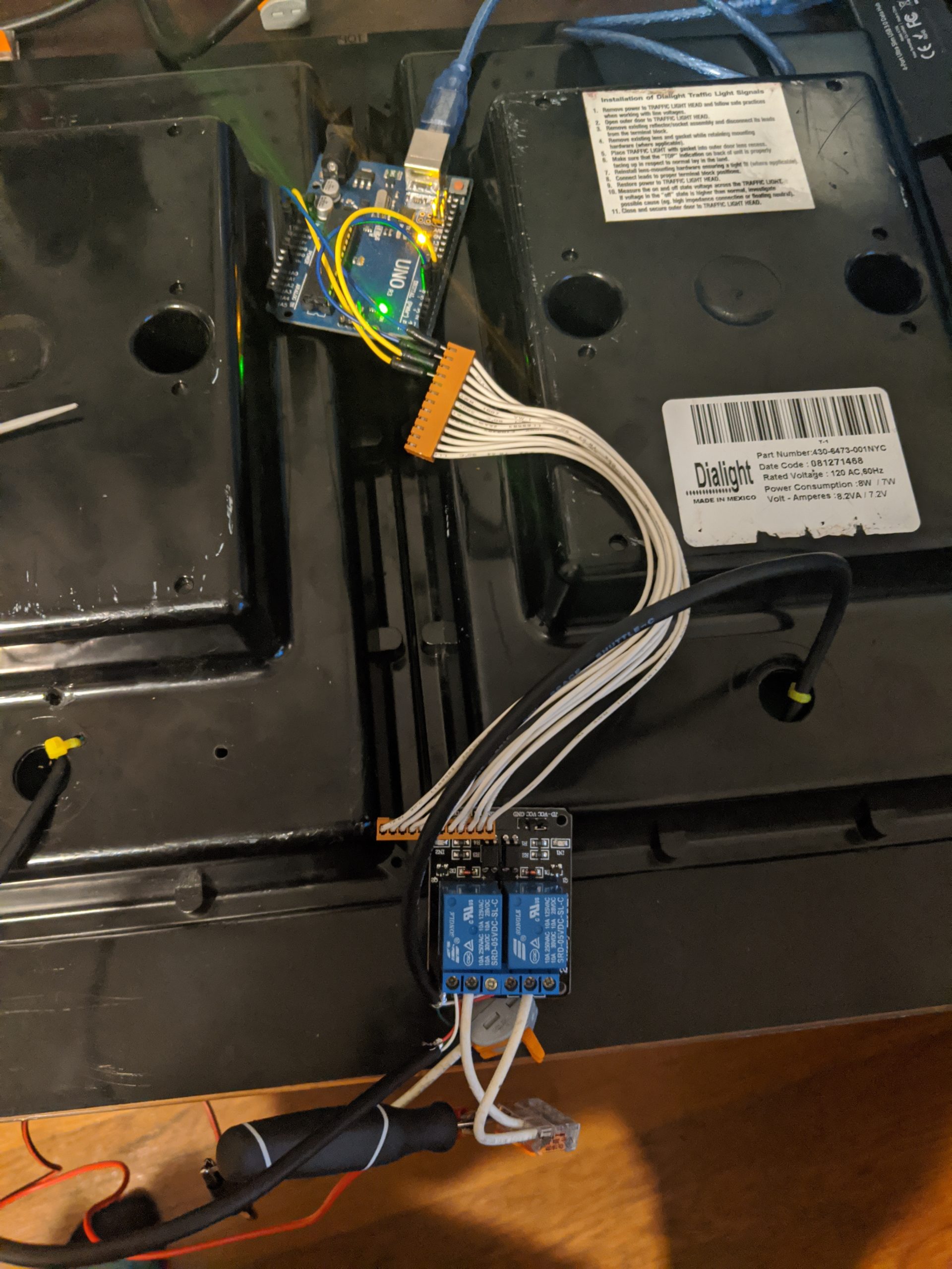
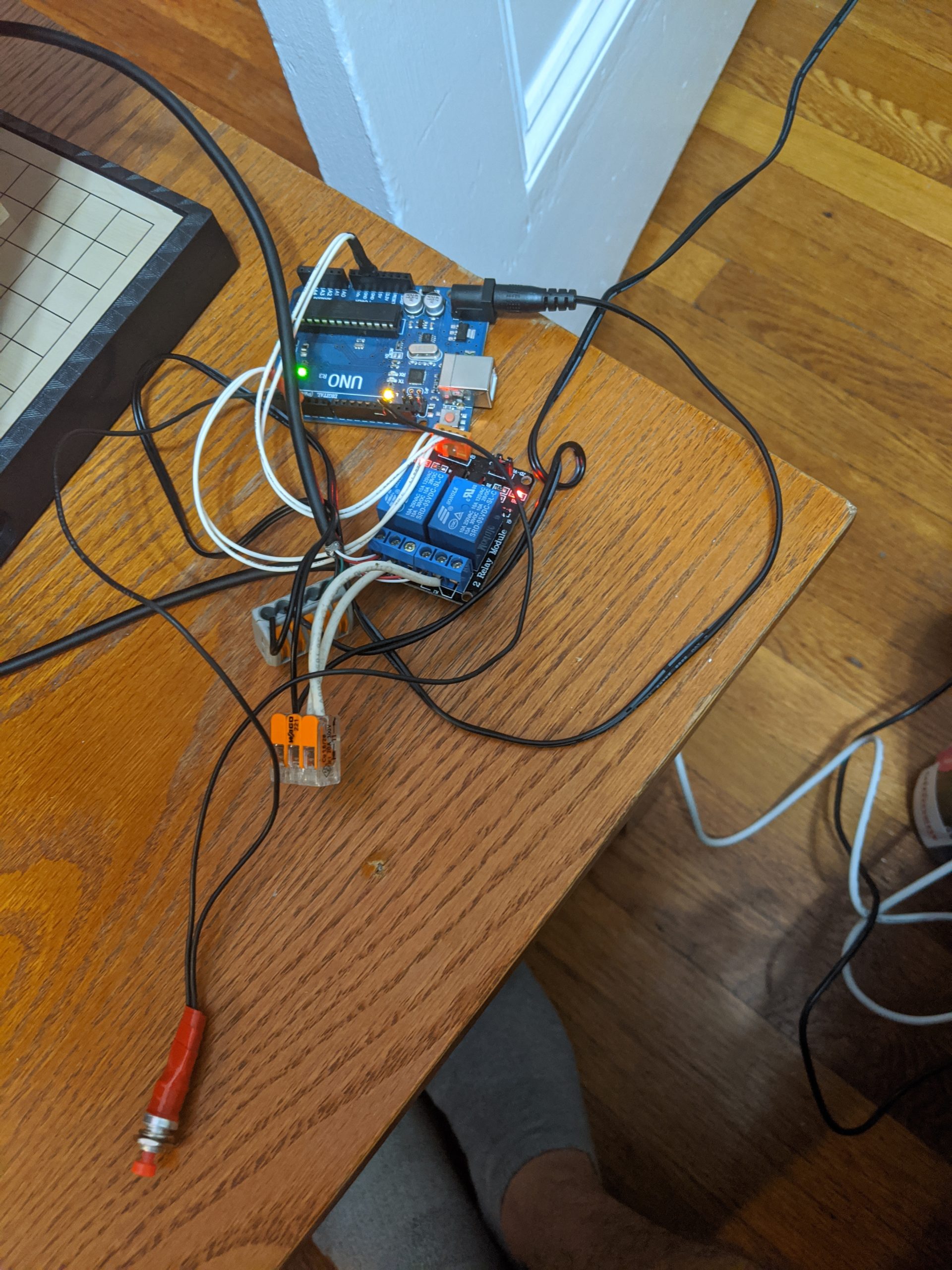
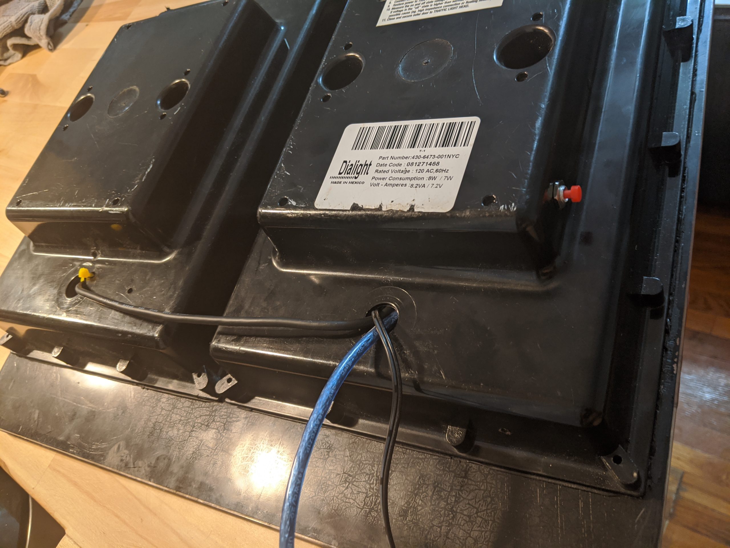
This project was to modify a street lamp so it can be used as a household lamp, and use an arduino and relay board so it can be configured to manually display a hand or walk sign, or automatically cycle through them all as if it was in use on a street. See the video demo to the right, and if you’re interested in learning more about how it was made read below.
Background:
When I was in high school my dad and I found the innards of a walk/don’t walk sign lying by the side of the street and pulled it out. For a few years I had the wires that came out of its spliced into a house style plug and it would light up when powered. At some point the power supply for the don’t walk hand failed, and after taking a look at it it doesn’t seem like it’s going to be repairable. My goal for this project is to take the whole thing apart, figure out how it works and wire it up to an arduino to sequentially flash the don’t walk/walk lights appropriately.

Physical Build:
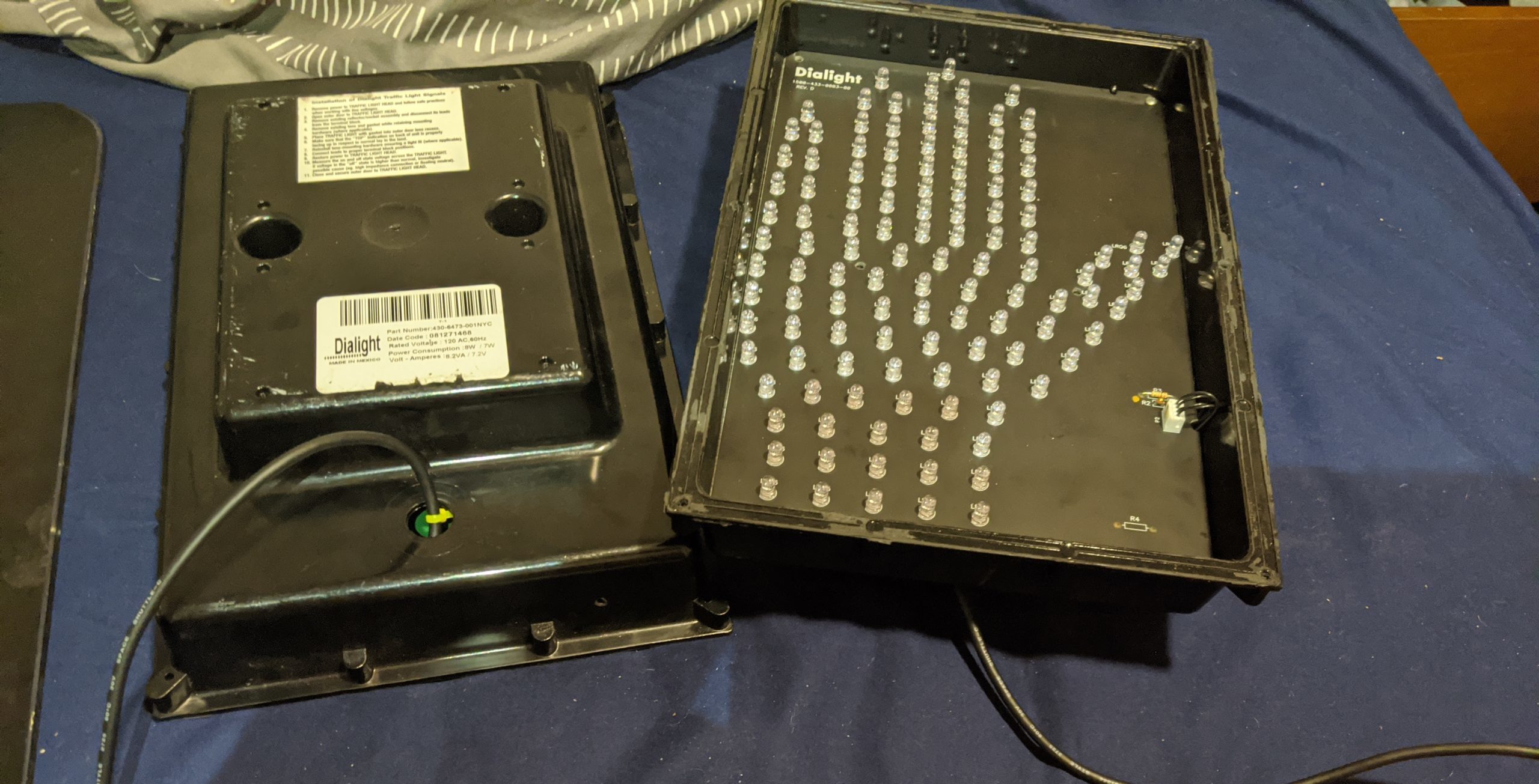
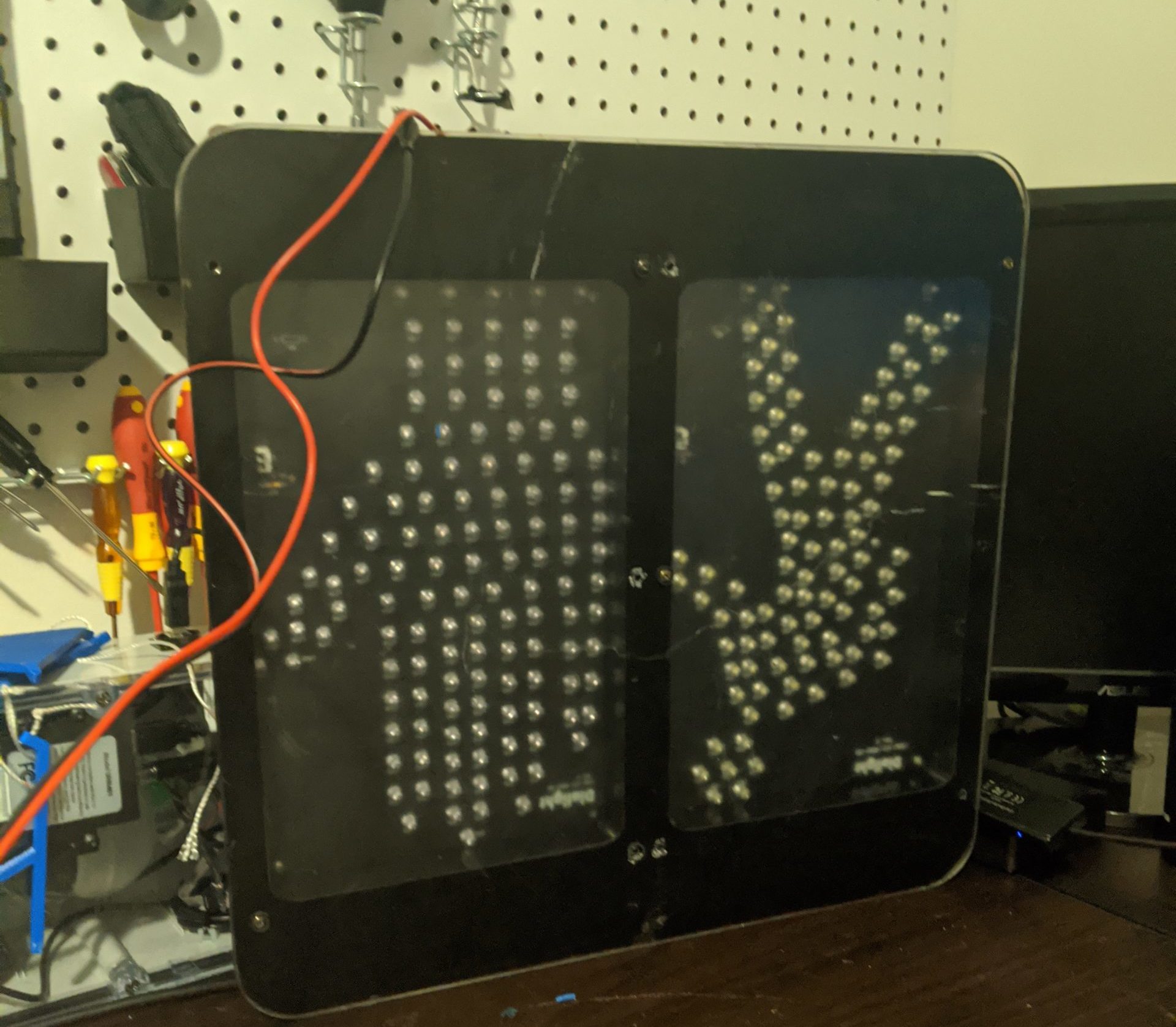
The light is made of three main parts, the two lamps (pictured below) and the front panel they screw into. Each lamp has an enclosure and a removable PCB with the LEDs on it. Originally the space behind the PCB was taken up by the power supply, but this is where I’ll be putting the electronics to power/control the lights.
Circuit Design:
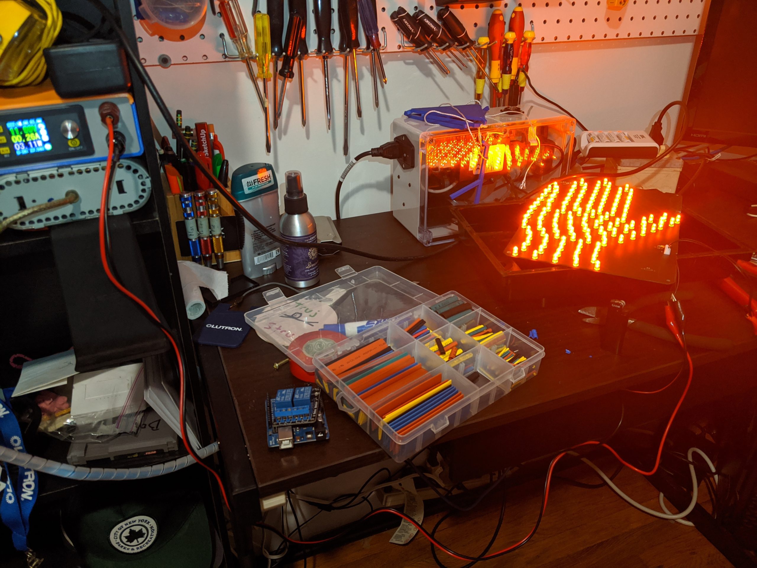
Using my new homemade variable power supply and some trace following I was able to reverse engineer the circuit on the LED panels and determine that at 12V they produce near peak brightness and use ~.3 W. 12V is convenient because the Arduino can be driven by 12V and I have plenty of 12V power supplies kicking around that can be donated to this project.
Below is the overall circuit design. The arduino and the LED boards are both powered by the 12v power supply, and the arduino drives the boards via a 2 relay board triggered by digital outputs on the arduino.

Building/Testing:
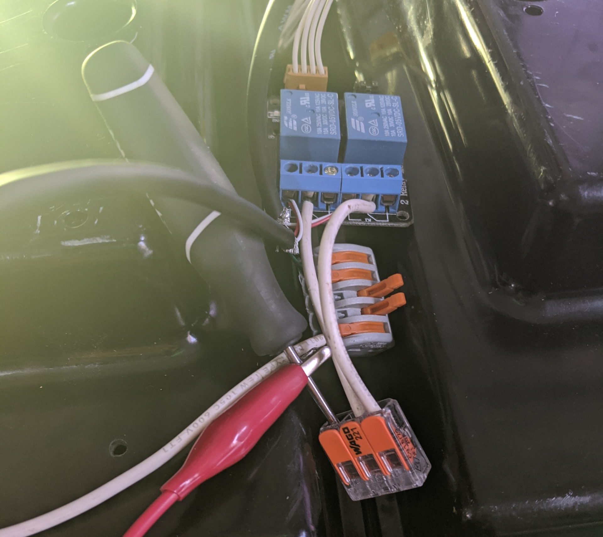
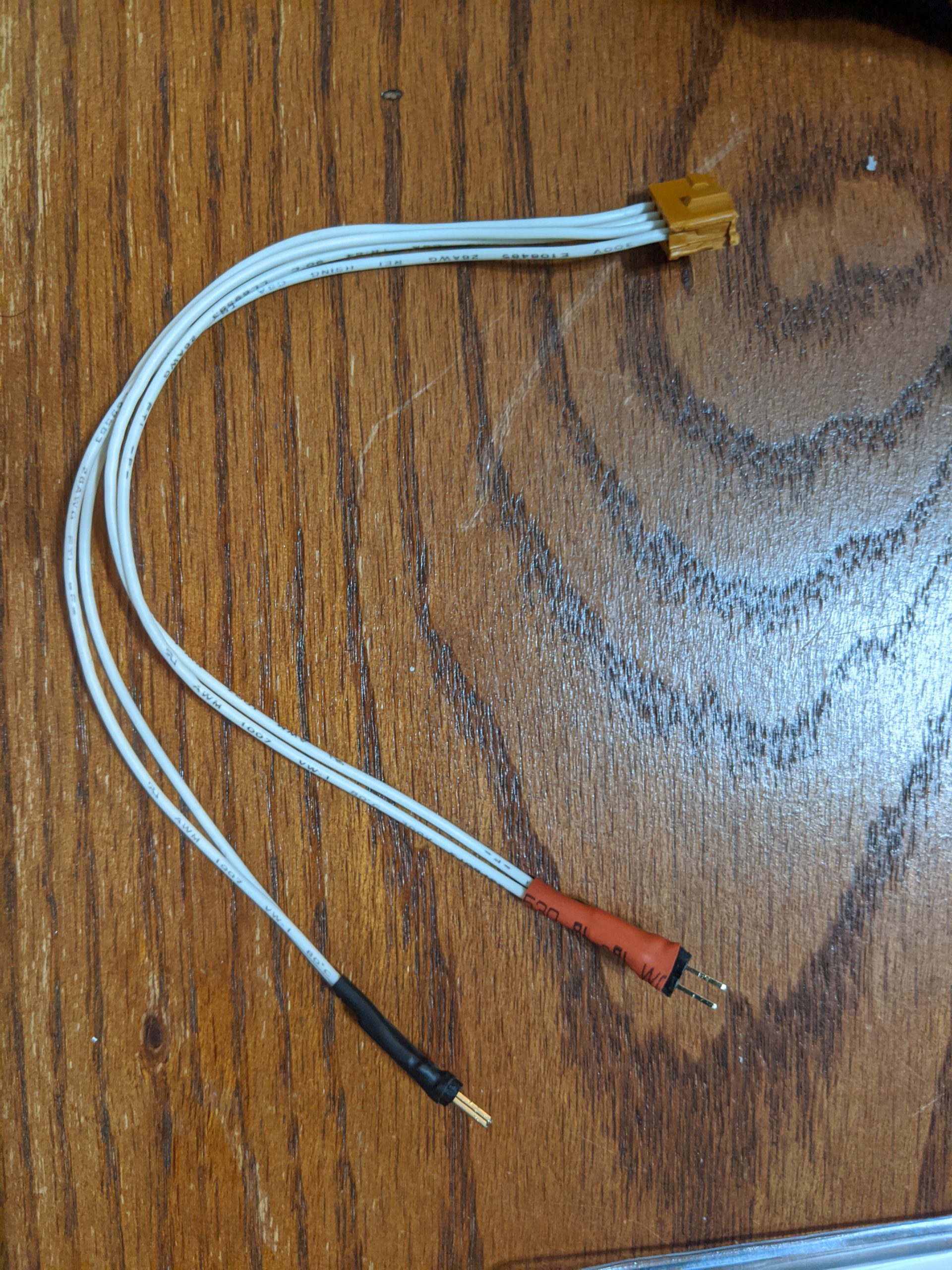
Video of testing the relay module. The clicking is louder then I’d like but I added some sound deadening to the enclosure and it helped a lot.
